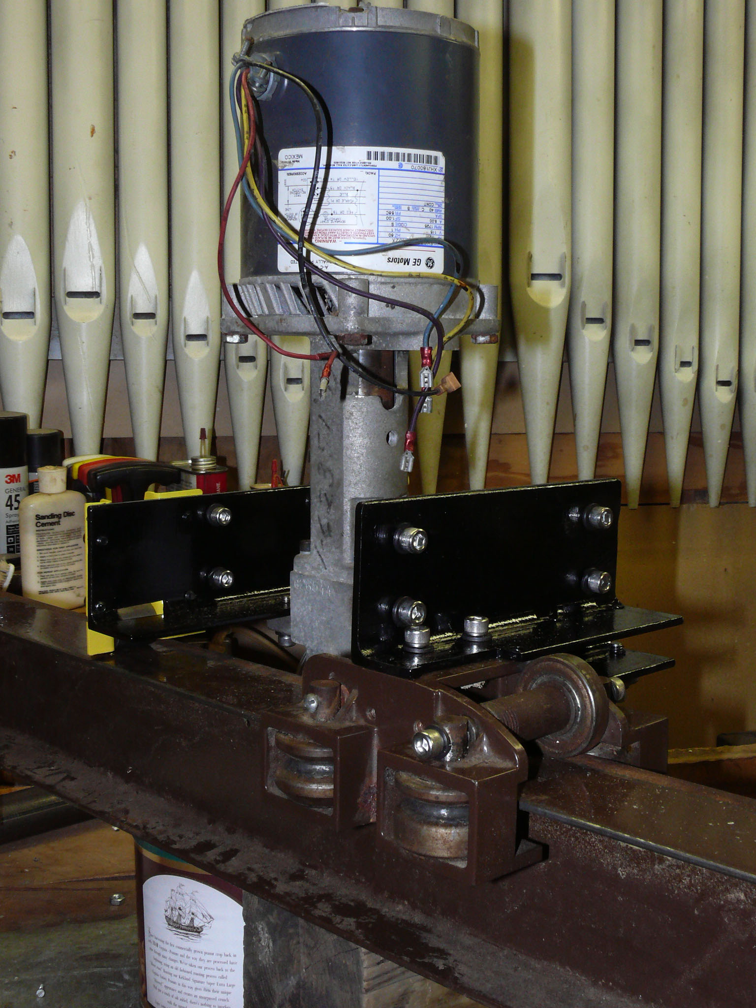
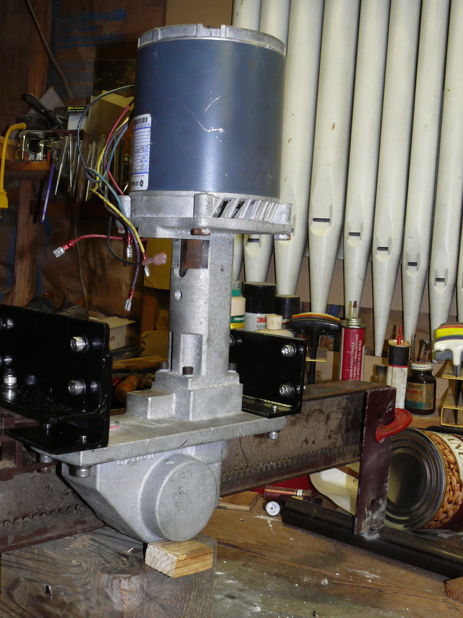
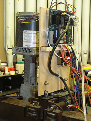
We lost the documentation for a Cheney Liberty Lift II Stair Chair (AKA Wecolator) that we wanted to repurpose as a simple electric moving carriage. The heavy steel "I" beam and rack & pinion design of this device seemed ideal so we needed to figure out how the Cheney WECO Controller (PCB 04795, Assembly 04794 (120VAC), Rev B) connects to the motor.
ThyssenKrupp, who purchased Cheney a number of years ago, has thus far acknowledged our request for connection information but not provided any information for this roughly 30 year old device.
The notes that follow are presented without any warrantee as to their fitness for any purpose whatsoever.
WARNING: These notes almost certainly contain errors.
Working on powerful mechanical devices such as the Cheney Wecolator or with electricity can be deadly,
DO NOT USE THESE NOTES UNLESS YOU UNDERSTAND THE DANGER!
What follows are our notes made while tracing the circuit to figure out how the motor is connected to the Cheney WECO Controller. In the end we got the Wecolater to operate going forwards and backwards on the track. All links are current as of March 2016.
1/2 HP, Serial # XHJ180070, Model 5XC32NNA402X, 110VAC, 60Hz, single phase Models 5KC32NNA402X and 5KC32NNA414X are both Class B insulated, 8Amp, 1/2 hp, 1725 RPM motor intended to be run with a 115 VAC 460 — 552 Mfd start capacitor under the control of a SINPAC®). There is no evidence of a motor run capacitor.
According to the label external motor controls must use a SINPAC® controlled start capacitor and offer two states:
- Black (#9) is connected to SINPAC 1 and via relay to Blue (#6)
And Yellow (#7) via relay to SINPAC pin 2- Black (#9) is connected to SINPAC 1 and via relay to Yellow (#7)
And Blue (#6) via relay to SINPAC 2
NOTE: Comparing the Motor schematic and the Cheney Controller reveals that pins 1 & 2 of the SINPAC® are reversed. Pin 1 is switched by the K1 relay on the on the board, The motor schematic calls for switching SINPAC pin 2. The motor's yellow lead must be connected to SINPAC pin 2 through K1 when K1 is not activated.
These two states let us determine the Cheney controller connections for motor leads labeled Blue (#6), Yellow (#7), and Black (probably swapped with Red) (#9).
Note: The "Blue" lead looks like Green to me. But it's the only one left (Purple and Yellow are 110VAC) and meter checking shows no leakage to the motor frame.
Judging by the connector the motor's Black and Red leads are swapped. The motor's Red lead should go to controller #9 and the motor's Black lead should go to the start capacitor connection to pin 3 of the SINPAC® (Red lead to W2 on the Cheney controller). The other side of the capacitor is also directly wired to the Cheney Controller (W1) with a white lead.
Note: Black and Red leads are a 12Ω start winding. Yellow to Blue is 0.8Ω run winding. Yellow to Purple is 0.8Ω run winding. CAUTION: Blue and Purple are strapped (0Ω). At 110 the "run" windings are in parallel reducing the resistence to around 0.4Ω (Ohm's law at 110VAC and 0.8Ω suggests a 275A draw that seems a bit high).
The Cheney Controller relies on a Rexnard Corp (Sterns Div.) model CV-40 (40 Amp 472104011UB1 4S Duty S9349 115V 50/60 Hz) SINPAC®) to disconnect the motor starter windings (Black and Blue motor leads) when the motor comes to speed. The SINPAC® does the same thing as a motor start switch. The SINPAC® was removed from the circuit and satisfactorily tested with a 25W 115VAC light bulb as described in Sterns P/N 8-078-393-00 pg. 5 Procedure for Checking SINPAC® Switches using Diagram 1.
See sinpacspecs.pdf (see sinpacspecs.pdf (reproduced from http://www.carbonbrush.com/sinpacspecs.pdf) for detailed information or SINPACSwitches.pdf for general information (from http://www.rexnord.com/ContentItems/TechLibrary/Documents/Stearns/ir_Series_SINPACSwitches_BriefOperatingDescription.aspx).
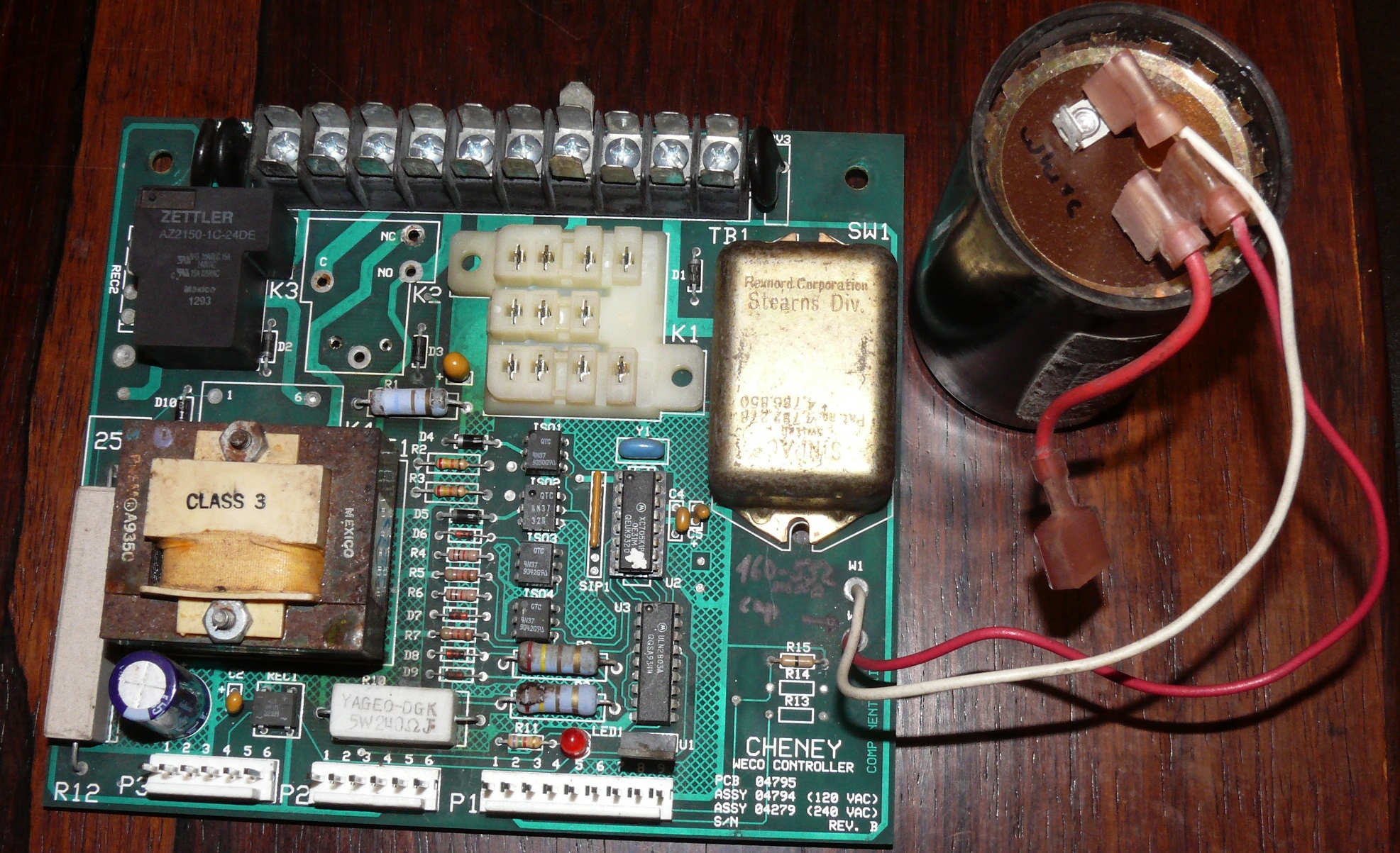
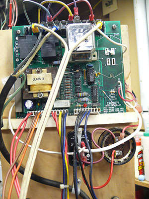
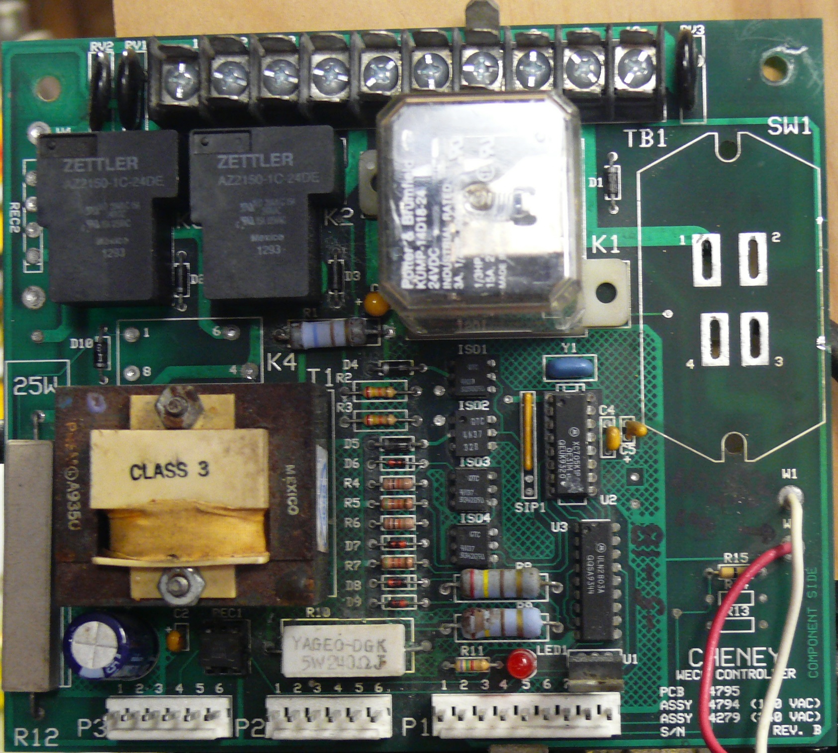
The SINPAC® was removed from the Cheney Controller for testing (see picture). Leads were added so the SINPAC® does not need to be permanently resoldered until this circuit analysis is complete.
PCB 04795, Assembly 04794 (120VAC), Rev B — no serial number visible.
Presumably the state of cuttable traces JP1, JP2, and JP3 is the only difference between the board we have and Assembly 04279 (240 VAC).
K1 was unplugged and K2 was removed (unsoldered) for this picture (click on image for a higher resolution version and access to an image with the SINPAC® removed):
Note: Motor Blue (3) and Motor Purple (7) are probably interchangeable.
Potter & Brumfield KUMP-14D18-24, 24 VDC Industrial rated 3A 1/2HP 600VAC, 1/3 HP 120VAC, 15A 277VAC. The 3 pole Double Throw relay seems a bit light for 1/2 HP but there is no sign of point burning. 2 poles (1, 2 &smp; 3 and 4, 5 & 6) are directly involved in motor control and the remaining pole (7, 8 & 9) is used for logic.
Both <1>K2 and K3 are American Zettler AZ2150-1C-24DC, 40A, SPDT (type "C"), with a 24VDC 660 Ohm coil. They have different NO and NC ratings. 1HP NO vs. 1/2HP NC or 30A NO and 15A NC inductive (see ZettlerRelay.pdf is reproduced from http://www.alliedelec.com/images/products/datasheets/bm/AMERICAN_ZETTLER_INC/70132353.pdf).
K2
This relay was removed for tracing (see pictures). NO connects the AMP flat male connector #4 and the JP2 end of the transformer. NC connects the AMP flat male connector #4 through the big ceramic 10 Ohm @ 10 Watt resistor (R12) to the NC contact of the other identical relay (K3). K2 switches AMP flat male connector #3.
K3
NO connects to AMP flat male connector #2 and the JP1 end of the transformer. NC connects through the big ceramic 10 Ohm @ 10 Watt resistor (R12) to the NC contact of the other identical relay (K2). K3 switches AMP flat male connector #6.
Here's the derived relay logic truth table for the K2 and K3 relays on the Cheney WECO Controller (PCB 04795).
The three pole K1 relay is is used to flip the polarity to the SINPAC for reversing the motor. The effect of K1 is shown in the alternatives for #6. #9 is also controlled by K1 but simply follows SINPAC1.
|
|
K2 INACTIVE |
|
K2 ENERGIZED |
|
K3 INACTIVE |
|
|
|
|
K3 ENERGIZED |
|
|
|
| K1 | K2 | K3 | Pin 1 | Pin 2 | Pin 3 | Pin 4 | Pin 5 | Pin 6 | Pin 7 | Pin 8 | Pin 9 | Pin 10 |
|---|---|---|---|---|---|---|---|---|---|---|---|---|
| — | — | — | 28VAC | 110 | #6 10?, ISO1&2 | 110 | 28VAC | #3-10?, #9, S2 | S1 | — | #6 & S2 | P1-1, P1-2, D9->ISO4-2 |
| X | — | — | 28VAC | 110 | #6 10?, ISO1&2 | 110 | 28VAC | #3-10?, S1 | #9, S2 | — | #7 & S2 | P1-1, P1-2, D9->ISO4-2 |
| X | X | — | 28VAC | 110 | 110(#4), ISO1&2 | 110 | 28VAC | S1 | #9, S2 | — | #7 & S2 | P1-1, P1-2, D9->ISO4-2 |
| X | — | X | 28VAC | 110 | ISO1&2 | 110 | 28VAC | 110(#2), S1 | #9, S2 | — | #7 & S2 | P1-1, P1-2, D9->ISO4-2 |
| — | X | — | 28VAC | 110 | 110(#4), ISO1&2 | 110 | 28VAC | #9, S2 | S1 | — | #6 & S2 | P1-1, P1-2, D9->ISO4-2 |
| — | X | X | 28VAC | 110 | 110(#4), ISO1&2 | 110 | 28VAC | 110(#2), #9, S2 | S1 | — | #6 & S2 | P1-1, P1-2, D9->ISO4-2 |
| — | — | X | 28VAC | 110 | ISO1&2 | 110 | 28VAC | 110(#2), #9, S2 | S1 | — | #6 & S2 | P1-1, P1-2, D9->ISO4-2 |
| X | X | X | 28VAC | 110 | 110(#4), ISO1&2 | 110 | 28VAC | 110(#2), S1 | #9, S2 | — | #7 & S2 | P1-1, P1-2, D9->ISO4-2 |
Permanent Connections
Pin 9 is always connected to S2 (SINPAC pin 2).
Pin 3 is always connected through a resistor & diode to ISO1 and ISO2.
Pins 4 & 2 provide continuous (un-switched) 110VAC to the low voltage logic.
AMP Spade Connectors (Pins) Not Controlled By Relays
AMP spade connectors Pin 1 (28 VAC shared with P2-4 & P2-2), Pin 8 (No Connection) and Pin 10 (connected to ISO4, P1-1 and P1-2), are not controlled by relays.
Relay Controlled AMP Spade Connectors (Pins)
The pins that change using relays are #3, #6 and #7:
K1 only switches Pin 7 from SI to #9 & S2.
K1 also straps Pin 9 to, Pin 6 when active (high) and straps Pin 9 to Pin 7 when inactive (low).
K2 puts 110VAC (from Pin 4) on pin 3 when active (high).
K3 puts 110VAC (from Pin 2) on pin 6 when active (high).
IF K2 and K3 are not active at the same time Pin 6 and Pin 3 are strapped together through 10Ω.
Prem SPW-1206 (see PremXfmr.pdf (from http://premmagnetics.com/Content/pdf/page8.pdf. The documentation is shaky and the pin numbering on our part corresponds to the SPW 1300 series. But there's not much question that it's dual SC power:
110VAC 220VAC JP1 ON CUT JP2 CUT ON JP3 ON CUT
Output(secondary windings) in parallel is 18V @ 5650 mA, is series it's 36V @ 280 mA (center tapped).
Judging by the value it is clearly a motor start capacitor: 460-552 mfd @ 110-125 VAC. [One suggestion is to add 2 watt 15K ohm resistor to bleed it down for safety when working around the capacitor.]. Example is DAYTON 2MDU3. It seems non-polar and connects to the white and red leads on the controller. The red lead side also goes to the red lead on the motor (see later comments about the liklihood that the red and black motor leads are swapped).
Some header connections are unused. They are greyed out.
The remaining connections are in three groups. The P1, P2 & P3 0.15" headers are labeled "P" followed by the header number, a dash and the pin number on that header The following is a best guess schematic if the P1, P2and P3 headers:
NOTE: "#1" us an AMP spade connector on the opposite side of the controller board.
Presumably the 10 AMP spade lugs on one side of the controller baoard do all the high current work.
The logic has to be derived from the circuit. The ten AMP spade lugs are labeled on the schematics with plain numbers or with a hash and a number.
Please appreciate that there are mistakes in the tables and schematics displayed here. "Buzzing out" or tracing a circuit board is tricky.
The U2 MCU (Micro Controller Unit) is a single 16 pin socketed XP705K1P IC (presumably a MC68HC70K1 variant). It's probably a one-time programmable clocked at 2.1MHz, with 32K, as a 52-PLCC for which I could not find a data sheet. It appears that the Motorola MC68HC705KJ1 is substantially the same (at least for pin assignments). In any event, the MCU has to be considered a black box since there is no way to access the firmware.
The remainder of the logic consists of a ULN2803A eight darlington driver IC (U3) and four 4N37 single channel TTL compatable Optocouplers (ISO1, ISO2, ISO3, and ISO4).
ISO1 and ISO1 appear to monitor the state of AMP connector #3. R4 & D6 exercise control over on ISO3. R6, R7, D7, D8, and D9 all seem to effect ISO4.
NOTE: U2 (68HC705K1) IRQ (pin 4), PA5 (pin 10), PA6 (pin 11), PA7 (pin 12) are pulled up to +5VDC (U1 pin 3) by SIP1 at pin 1. The individual 20K pull-up resistors aren't shown in the schematic above. SIP1-1 is +5 VDC from U1-3. SIP6&7 appear unused.
NOTE: U2-PA4 (pin 9) goes to U3-4.
NOTE: K4 is not installed.
NOTE: ISO1-5 & ISO2-5 hold U2-11 high at +5VDC when K2 and K3 are not active. If either or both K2 or K3 are active a +5VDC 60 pulse per second signal is sent to U2-11.
List of Resistive Components
ID Value Power Tolerance R1 360 2W 5% R2 24K 1/4W 5% R3 24K 1/4W 5% R4 1K 1/8W 10% R5 5.1K 1/8W 5% R6 1K 1/8W 10% R7 5.1K 1/8W 5% R8 220 2W 5% R9 220 2W 5% R10 240 5W 10% R11 1.5 1/8W 5% SIP1 22K (6x-1-223) 5 resistor SIP
List of Key Passive & Miscellaneous Components
ID Value C1 1,000 uF @35VDC Electrotytic C2 334 pF @35 VDC Tantalum C3 10 uF @35 VDC Tantalum C4 100,000 pf ceramic C5 2.2 uF @ 16VDC Tantalum Y1 3.00 MHz ceramic resonator U1 LM340TS power transistor
Connector Routes
P1 Pin Function Connection 1 P1-pin2 & D8+ & D9- & AMP #10 None 2 P1-pin1 & D8+ & D9- & AMP #10 None 3* K1 NC contact 3 NOMC Switch 4* P1-pin 6 & P3-pin 5 & +18VDC* Black 5* K1 NO contact 6 Blue 6* P1-pin 4 & P3-pin 5 & +18VDC** NOMC Switch 7 N/C None 8 P1-pin 9 & P3-pin 3 & -18VDC** & AMP #5 None 9 P1-pin 8 & P3-pin 3 & -18VDC** & AMP #5 None
P2 Pin Function Connection 1 18VAC(-) jumped to P2-2 2 P3-pin 1 jumped to P2-1 3* N/C None 4* 18VAC(+) P3-pin 2 & AMP #1 Brown 5* D7+ Orange 6* D6- None
P3 Pin Function Connection 1* P2-pin2 Red (fuse) 2* 18VAC(+)** P2-pin 4 & AMP #1 Red 3 P1-pin8&9 & -18VDC** None 4* LED1 - Yellow 5* P1-pin4&6 & +18VDC** Black 6* N/C Blue
* Pin is connected to external wiring
** Determined from the trace
NOTE: I added a socket for REC1 so it can be removed for tracing. REC1 reinserts with the DC output closest to the transformer.
A distinction is made between recrifier AC inputs. In the notations here the input under the + output
is labeled with "(+)" to distinguish the 18 volt AC paths from the transformer.
Starting with low voltage AC (probably from the red wire to AMP pin 1) the direction controller returns either positive or negative half wave DC (probably via the blue wire to AMP pin 10). There are two switch/diode assemblies connected in parallel which raises the possibility that the original AC would be reconstituted if one switch is depressed for "UP" while the other is depressed for "DOWN".
Direction is decoded into opposite phase 60 pps pulse trains by ISO3 and ISO4 and sent to U2-5 and U2-6 respectively. It's pretty clear that U2 must use a watchdog scheme with an internal timer. A 17ms timer is started for the direction (perhaps with an interrupt for each direction) and the appropriate direction flag is set. If there's no confirming pulse when the timer expires the direction flag is cleared. The main software need only poll the flags to change motor direction or and stop the motor when neither or both flags are set.
+5V pulse trains appear on U2-5, U2-6, and U2-11.
ISO3 generates the pulse train for U2-5.
ISO4 generates the pulse train for U2-6.
ISO1 and ISO2 generates the pulse train for U2-11.
All the pulse trains except one are the complement of the 60HZ. They are high when the 60Hz is low and low when the 60HZ is high — except U2-11 when K2 is active. When K2 is active U2-11 follows the 60Hz with a slight lag.
What is not clear is what happens at ISO1 and ISO2 at U2-11 when K2 and K3 are active. The output seems to latch into a pulse train that's complementary to the 60Hz. This seems odd but we didn't investigate further.
Motor and Mains Power
The following are the minimum motor connections to the ten AMP spade connectors on one edge of the Cheney WECO Controller:
Pin Number Wire Color 2 Mains 110VAC 3 Blue (or Purple) 4 Mains 110VAC 6 Yellow 7 Purple (or Blue) 9 Black
Note: Pins 3 & pin 7 are effectively strapped by the motor's blue and purple leads.
Note: Something of a mystery are all the AMP spade connectors at #7.
Note: The 5 watt 240Ω R10 ceramic resistor runs awfully hot at idle. The PCB shows no signs of the expected scorching. The transformer also runs quite warm at idle. No other components seemed to be straining; but, even though the Wecolator appears to run correctly, something — perhaps a connection — may be wrong or an external current limiter may be needed at the NC limit switches on P1-4.
Direction Controller
The two wire direction controller works connected to the common on AMP pin 1 and the signal (polarized by the diodes in the direction switch) to AMP pin 10. This results in a signal at U2-5 for one direction or U2-6 for the other direction. The signal is a 60 pulse per second pulse train at +5VDC. When not activated U2-5 and/or U2-6 are pulled down to -5VDC (common).
We did not check to see what happens if two direction controllers, connected in parallel, are each toggled for opposite directions.
P1 Header
Pin Number Function 1 P1-2 and probably
supports direction SW2 P1-1 and probably
supports direction SW3 K1-3 NC 4 P6 and +28VDC 5 NC Switch A 6 P4 and +28VDC 7 NC Switch B 8 Not used 9 Not used
P2 Header
Pin Number Function 1 28 VAC to external
1/2 Amp fuse2 P3-1 3 Not used 4 From external 1/2 Amp
fuse to AC side of low
voltage rectifier5 Neg trigger for
direction6 Pos trigger for
direction
P3 Header
Pin Number Function 1 External strap to
P3-22 External strap to
P3-13 Not used 4 Slave LED 5 Slave LED 6 Not used
An external controller can be used in place of U2 with the following connections (+5 must be applied to activate a relay):
Pin Number Function 1 +5 VDC 2 K2 Relay 5 Direction A* 6 Direction B* 7 K1 Relay 8 K3 Relay 14 -5 VDC
*Read only. Most likely +5VDC at 60 pulses per second.
Note: Both pins 2 & 8 of the U2 socket must be raised to +5 VDC to start the motor. Pin 7 of the U2 socket controls the direction — Forward if pin 7 floats (maybe -5 VDC would work) -OR- Reverse if pin 7 is +5 VDC.
For the curious here's is the test jig that runs. Click on the image to get a higher resolution image.
March 22, 2016
![]()
![]() Site
Copyright 2016 Aza D. Oberman, all rights reserved
Site
Copyright 2016 Aza D. Oberman, all rights reserved
This nonsense is presented "as-is" and not endorsed by Image Logic Corporation
index.html 160315